 EN
Solder Joint Cracks in Thin Wire Metal Eyewear Frames: Causes and Corrective Actions
Discover thermal, material, and fatigue causes—and proven corrective actions for manufacturers. Optimize yield now.
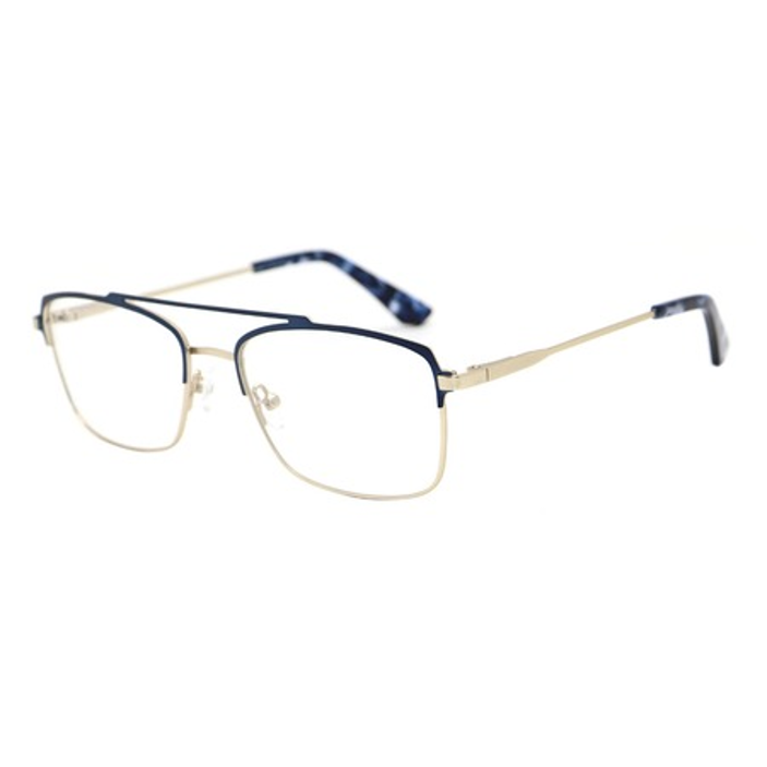
Solder joint cracks represent one of the most persistent quality challenges in the manufacturing of metal eyewear frames, particularly in thin-wire designs where structural integrity is critical. These microscopic to visible fractures develop at connection points where frame components are joined, compromising both the aesthetic appeal and functional durability of the final product. Understanding the root causes and implementing targeted corrective actions is essential for manufacturers committed to delivering reliable, long-lasting eyewear to their customers.
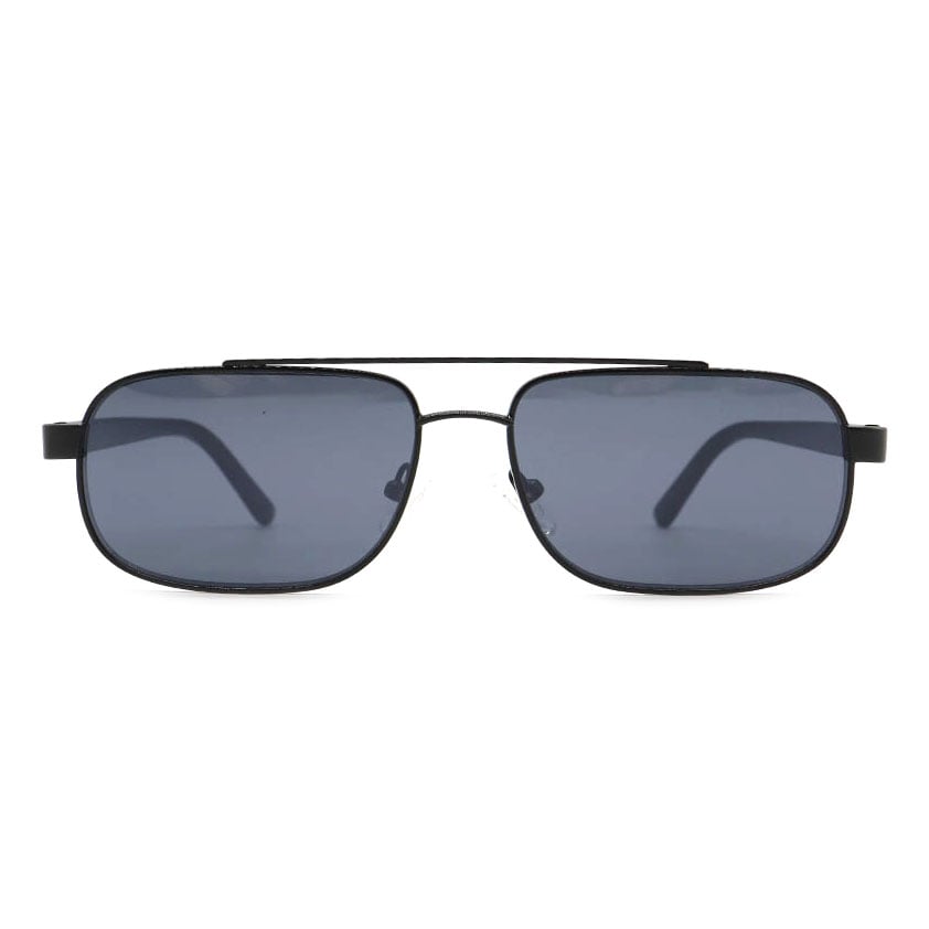
The problem becomes especially acute in thin-wire metal frames because the reduced cross-sectional area of the wire material amplifies stress concentration at solder joints. When a wearer flexes their eyewear during normal use—putting them on, adjusting them, or inadvertently pressing them against surfaces—the thin wire material experiences proportionally greater strain. Solder joints, which are inherently the weakest points in the frame structure, become susceptible to cracking under these conditions.
Understanding Solder Joint Failure Mechanisms
Thermal Stress and Cooling Inconsistencies
During the soldering process, metal frames and solder experience rapid heating and cooling cycles. The base metal material—whether stainless steel eyewear components or alloy frames—and the solder itself have different thermal expansion coefficients. When the joint cools after soldering, these materials contract at different rates, creating residual tensile stress at the interface. In thin-wire designs, this thermal stress is particularly problematic because the small diameter of the wire provides minimal buffer for stress distribution.
If the cooling process is too rapid or uneven, thermal gradients form within the joint, causing localized weakening. Controlling furnace temperature profiles during the cooling phase significantly reduces the likelihood of crack initiation. Additionally, when metal frames are subjected to temperature fluctuations during shipping or storage—exposure to cold warehouses followed by warm retail environments—the joint experiences repeated micro-strain cycles that can propagate existing microcracks into visible fractures.
Material Composition and Joint Preparation
The choice of solder alloy directly impacts joint reliability in metal eyewear applications. Lead-free solders, increasingly mandated for consumer products, often exhibit lower ductility and higher brittleness compared to traditional lead-based formulations. When used with certain stainless steel eyewear or alloy frames materials, the solder may not wet the base metal properly, creating incomplete bonding that appears as voids or delamination within the joint. These defects serve as stress concentration points where cracks initiate and propagate.
Base metal surface condition is equally critical. Oxidation on stainless steel eyewear components or contamination on alloy frames prevents the solder from forming a continuous metallurgical bond. Even microscopic oxide layers create barriers that force the solder to bond only to the surface rather than forming a strong intermetallic layer. Without adequate mechanical inter-locking and chemical bonding between the solder and the metal frames, the joint becomes inherently fragile.
Mechanical Stress Concentration in Thin-Wire Designs
Stress Distribution and Fatigue Loading
Thin-wire metal frames experience concentrated stress at solder joints because the reduced material mass offers limited cross-sectional area to distribute applied loads. During daily use, flexing stress—from putting on and removing eyewear, or from pressure during wear—creates cyclic loading at each joint. Unlike thicker frame materials that can distribute stress more broadly, thin metal eyewear wire concentrates this force acutely at the joint interface.
Fatigue cracking occurs when the solder joint experiences repeated stress cycles at levels below the ultimate tensile strength of the material. Solder is particularly susceptible to fatigue because its crystalline structure and low ductility make it prone to crack initiation under cyclic loading. Each small flex introduces a micro-strain that, over hundreds of thousands of cycles, accumulates into a visible crack. This is why some metal eyewear frames develop cracks only after weeks or months of normal use, even though the soldering process itself may have appeared successful initially.
Joint Geometry and Stress Concentration Factors
The geometry of the solder joint significantly influences stress distribution. Sharp, angular joint profiles create stress concentration factors that amplify the local stress beyond the nominal applied load. In thin-wire metal frames, the transition from the wire to the solder fillet is critical—a concave or abrupt profile concentrates stress, while a smooth, well-formed fillet distributes it more gradually. Poor soldering technique that produces inadequate fillet geometry creates stress risers where cracking preferentially initiates.
Additionally, the joint's position relative to the wire's neutral axis matters. When solder is applied off-center or unevenly around a thin cylindrical wire, the joint exhibits asymmetric stiffness. This asymmetry causes the wire to flex preferentially at the stiff joint, creating bending stress concentration. Controlling solder placement and ensuring circumferential wetting of the joint significantly improves the stress distribution profile.
Corrective Actions and Quality Improvements
Process Control and Joint Optimization
Manufacturers of metal eyewear should implement rigorous soldering process controls to minimize crack risk. First, controlling the heating rate and peak temperature during soldering ensures proper solder wetting and metallurgical bonding without excessive residual stress. Using a temperature-controlled reflow profile—slow ramp-up, appropriate dwell time at peak temperature, and controlled cooling—produces more ductile solder joints with reduced internal defects. For stainless steel eyewear and alloy frames, selecting a compatible solder alloy and flux system is essential; testing different lead-free formulations may reveal options that wet specific base metals more effectively.
Joint geometry should be optimized by ensuring adequate fillet formation. Using solder paste with appropriate viscosity and particle size, combined with precise placement, produces consistent fillet profiles. Employing fixtures that position the thin wire correctly relative to the heat source ensures uniform heating and even solder flow. Training operators to recognize proper solder wetting—a smooth, continuous fillet with concave side profiles—helps catch geometry defects before components progress to finishing.
Material and Design Interventions
Consider post-soldering stress-relief heat treatments. A controlled heating cycle that brings the assembled metal frames to a specific temperature for a defined period allows the solder to recrystallize and residual stresses to redistribute. This annealing process, commonly applied in precision manufacturing, significantly improves fatigue resistance of solder joints. For thin-wire metal eyewear, even a modest stress-relief cycle can substantially extend service life.
From a design perspective, engineers should evaluate whether joint location and loading can be modified. Positioning solder joints in areas that experience lower cyclic stress, or reinforcing the joint with additional material or design features, reduces fatigue crack risk. Some manufacturers incorporate mechanical fastening or adhesive bonding in combination with soldering, creating redundant load paths that prevent complete failure if a solder joint develops a crack.
Inspection and Quality Assurance
Implementing rigorous inspection protocols detects cracked joints before finished eyewear reaches customers. Visual inspection under magnification identifies visible cracks, but microscopic defects require more sophisticated methods. X-ray or computed tomography imaging reveals internal voids and delamination within solder joints that may not yet be visible but represent incipient failure sites. Pull testing or bend testing on samples from each production batch validates that joints meet strength requirements before full-scale production.
Accelerated life testing—subjecting sample metal frames to repetitive flexing, thermal cycling, or environmental exposure—identifies potential crack initiation under controlled conditions. If samples pass accelerated testing, the production process and materials are more likely to produce field-durable eyewear. When failures occur during testing, root cause investigation can pinpoint whether the issue stems from thermal stress, material composition, joint geometry, or fatigue loading, enabling targeted corrective action.
FAQ
What are the primary causes of solder joint cracks in thin-wire metal frames?
Solder joint cracks in thin-wire metal eyewear result primarily from three mechanisms: thermal stress created by differential cooling rates during soldering, material incompatibility between the solder alloy and base metal, and cyclic fatigue loading from normal flexing and wear. The reduced cross-sectional area of thin wire amplifies stress concentration at joints, making them particularly vulnerable. Poor surface preparation, inadequate joint geometry, and inadequate ductility in lead-free solder alloys compound the problem. Understanding these root causes allows manufacturers to implement targeted corrective measures.
How can manufacturers reduce the risk of solder joint cracking in metal eyewear production?
Corrective actions include implementing precise temperature profiles during the soldering process, ensuring slow ramp-up and controlled cooling to reduce residual stress. Selecting solder alloys compatible with the specific stainless steel eyewear or alloy frames being used improves joint ductility and wetting. Post-soldering stress-relief heat treatment allows residual stresses to redistribute, improving fatigue resistance.
Why are thin-wire metal frames more susceptible to solder joint cracks than thicker frames?
Thin-wire designs concentrate stress at solder joints because the reduced cross-sectional area of the wire provides minimal material to distribute applied loads. During normal use—flexing, pressing, or adjusting the eyewear—the thin wire experiences proportionally greater strain at the joint. Thicker metal frames distribute stress over a larger material volume, reducing peak stress at the joint.